
Automated Equipment Assembly / Automation Equipment

Multi-Material Die-Cut Component Kit for Automation Equipment

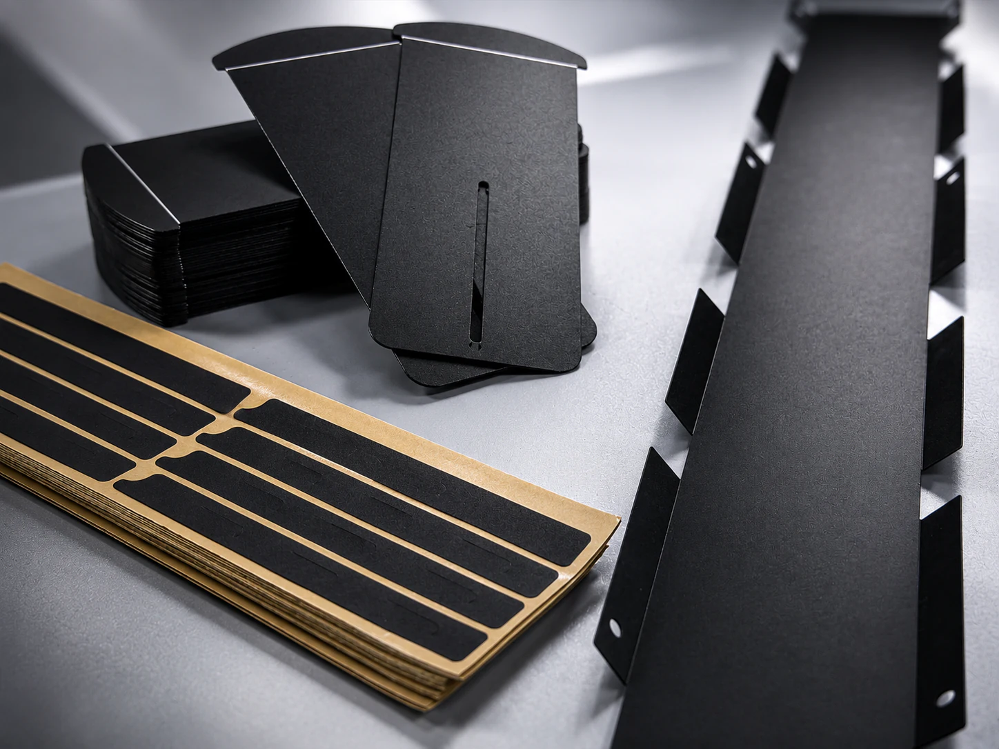
A coordinated kit of protective films, cushioning foams, adhesive gaskets, and support components prepared for automated equipment assembly.

Precision die-cut functional components for automation equipment assemblies
Representative converted component formats for this application type.

PROJECT SNAPSHOT

Application

Coordinated converted component kit for automated equipment assembly

Materials

Protective films, cushioning foams, adhesive gaskets, and insulation or support films

Converting Processes

Stack-up review, lamination, tooling preparation, precision die-cutting, and component kitting

Verification Focus

Part geometry, foam thickness, adhesive liner handling, component identification, kit completeness, and assembly fit

ENGINEERING RESPONSE

Project Approach

APPROACH_01

Challenge

Automation equipment assemblies can require several converted parts with different material behavior, thickness, liner format, and installation sequence. Geometry and identification must remain clear across the kit so protective films, cushioning foams, adhesive gaskets, and support components can be handled in the intended assembly order.

APPROACH_02

Engineering Response

Labelsun reviews the component drawings as one assembly set, including material stack-ups, mating interfaces, foam thickness, adhesive and liner construction, part identification, packaging sequence, and installation method. Tooling and converting routes are planned around both individual part requirements and kit-level handling.

APPROACH_03

Converted Output

Application-specific protective films, cushioning foams, adhesive gaskets, insulation parts, and support components are prepared as a coordinated kit for prototype review and controlled production preparation.

DEVELOPMENT ROUTE

Development & Verification Route

STEP 01

Assembly & Kit Review

Review component drawings, mating locations, installation order, part identification, and equipment assembly requirements.

STEP 02

Material & Stack-Up Planning

Evaluate protective films, foam layers, adhesive gaskets, support films, liner formats, and lamination requirements.

STEP 03

Prototype & Kit Verification

Prepare samples and review geometry, foam thickness, liner handling, component identification, kit completeness, and assembly fit.

STEP 04

Process Preparation & Release

Confirm the approved parts, tooling and converting route, kit presentation, inspection focus, and production-release requirements.

VERIFICATION & RELEASE

Verification & Production Release

Verification focuses on individual part geometry, foam thickness, adhesive and liner condition, component identification, kit completeness, and assembly fit. Inspection points and production release records are defined for the approved component set and presentation format.

Part geometry verification
Foam thickness review
Adhesive and liner check
Component identification review
Kit completeness check
Assembly-fit and release record review

RELATED CAPABILITIES

Related Manufacturing Capabilities

START A SIMILAR PROGRAM

Discuss a Similar Manufacturing Program

Share drawings, material stack-up requirements, assembly conditions, or sample needs for engineering review.