
PRECISION CONVERTING CAPABILITY
Precision Die Cutting for Functional Converted Components
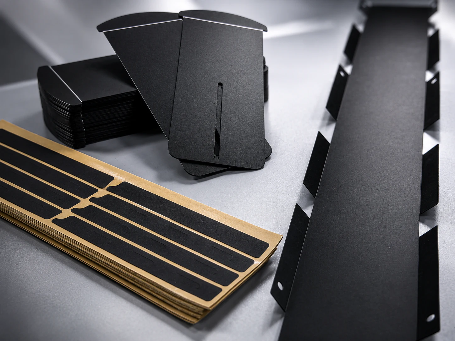
Labelsun supports flatbed and rotary die-cutting for films, foams, adhesives, insulation materials, graphite sheets, EMI materials, and multi-layer converted components. From drawing review and material selection to production tooling, lamination, liner design, and dimensional inspection, we help OEM teams convert approved component constructions through a repeatable production route.
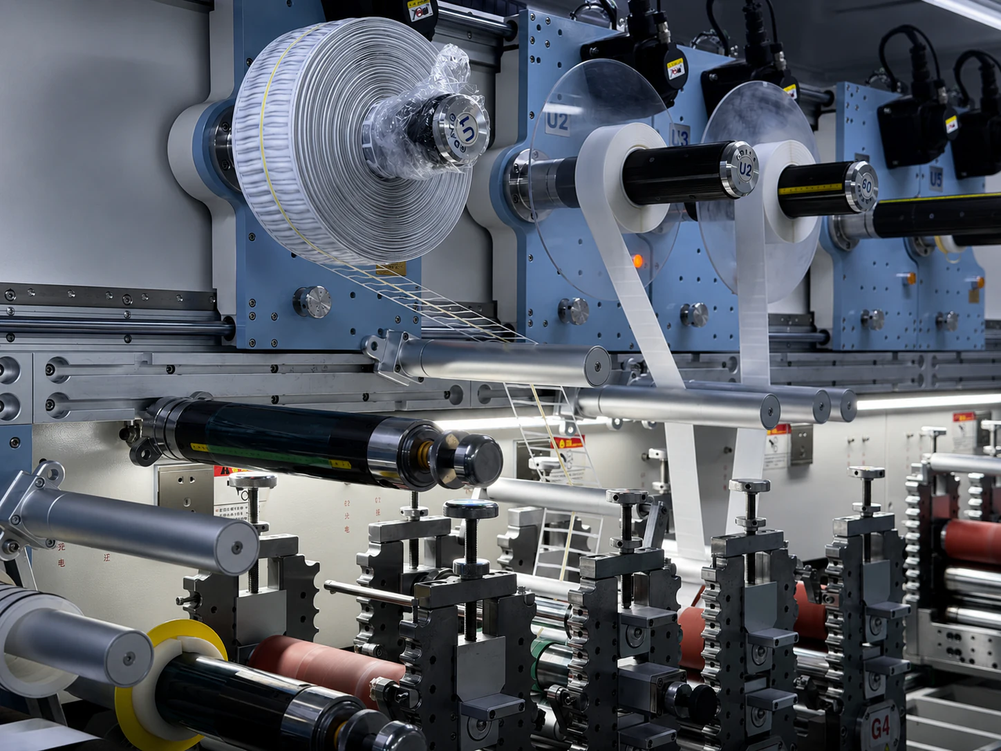
Roll-fed converting for films, adhesives, liners, and multi-layer materials.
PROCESS CONTROL
+/- 0.03 mm
Achievable depending on material, part geometry, and process route.
OEM SUPPORT
Production Route Support
Tooling, lamination, liner strategy, and inspection planning aligned with repeat manufacturing.
Capability Overview
Why Precision Die Cutting Matters
Precision die-cutting affects part fit, assembly efficiency, adhesive placement, release behavior, and dimensional consistency. For functional materials, the process must account for material thickness, compression, liner release, adhesive flow, cutting tolerance, and batch repeatability.
Fit & Alignment
Fit & Alignment
Part geometry, hole location, and edge quality influence how converted components register during downstream assembly.
Clean Release
Clean Release
Kiss-cut depth, liner construction, and adhesive behavior affect peel stability and operator handling during application.
Multi-Material Stability
Multi-Material Stability
Films, foams, adhesives, graphite, and conductive materials must remain stable through lamination, cutting, and release.
Repeatable Production
Repeatable Production
Tooling route, process verification, and dimensional checks help maintain batch consistency from approved sample through repeat production runs.
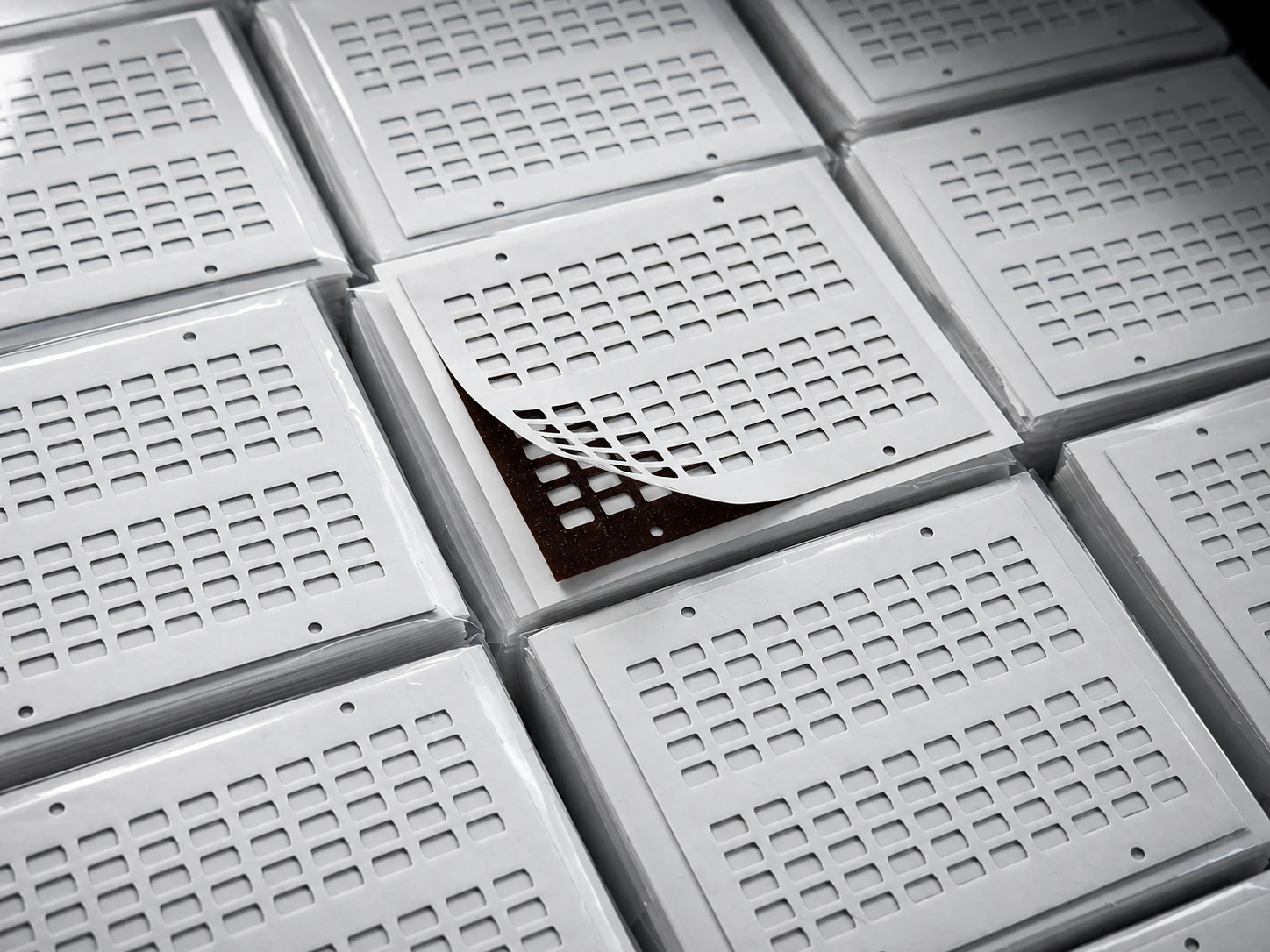
FINISHED COMPONENT EVIDENCE
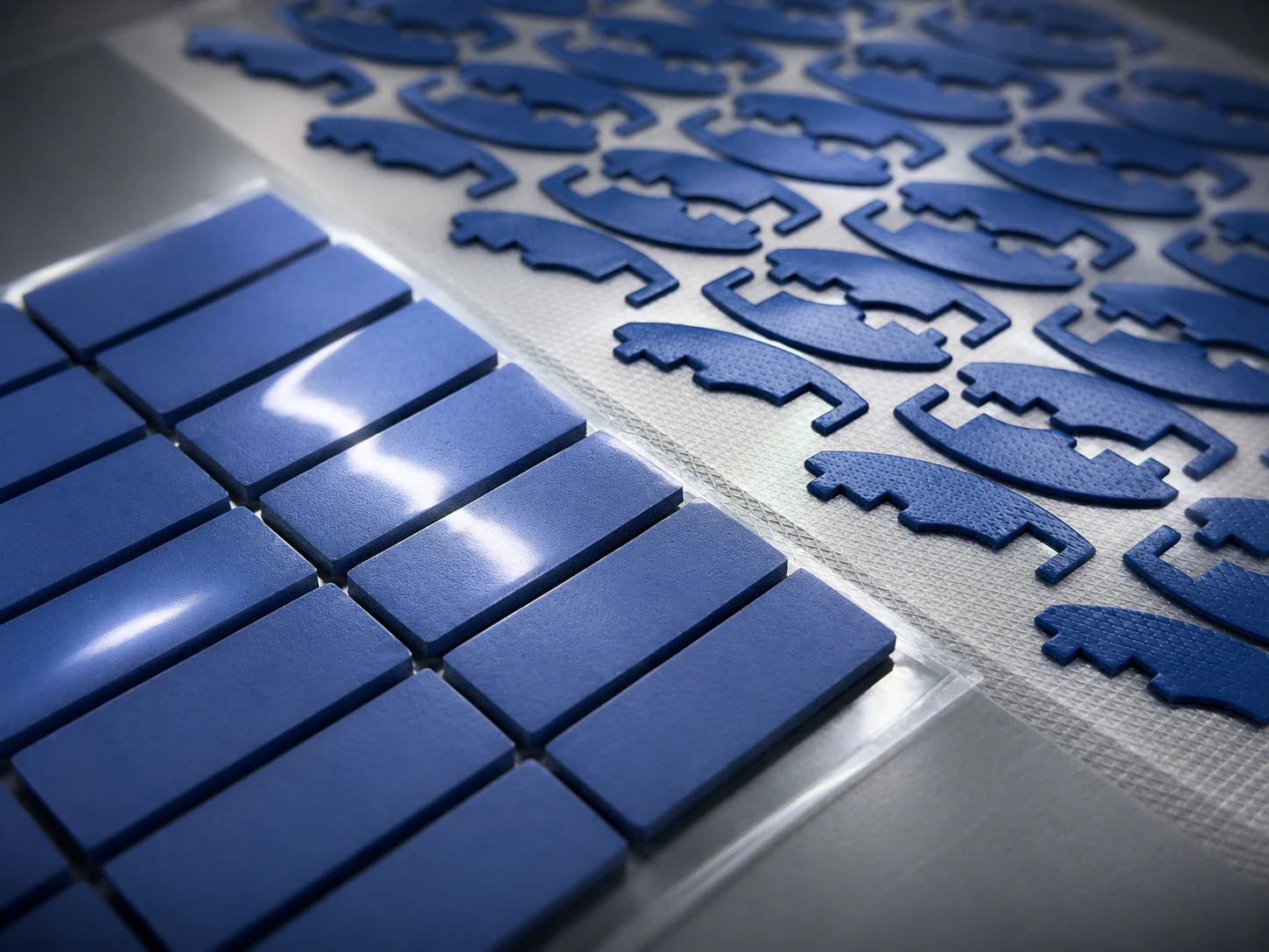
Laminated PI Die-Cut Structures
Laminated PI die-cut component structures with repeated cutouts, release layers, and finished component format.
What We Support
Die-Cutting Capabilities
Flatbed Die Cutting
Suitable for thicker materials, lower-volume runs, and complex contours requiring controlled press cutting.
Rotary Die Cutting
Continuous converting route for films, adhesives, and high-repeat geometries prepared for scaled OEM output.
Kiss Cutting
Controlled face-stock cutting while preserving liner integrity for clean peel, tab design, and assembly handling.
Through Cutting
Full-depth cutting for standalone parts, sheet formats, and thicker constructions that require complete separation.
Multi-Layer Lamination
Integrated stack-up building for adhesive, insulation, shielding, and thermal constructions before final converting.
Release Liner Design
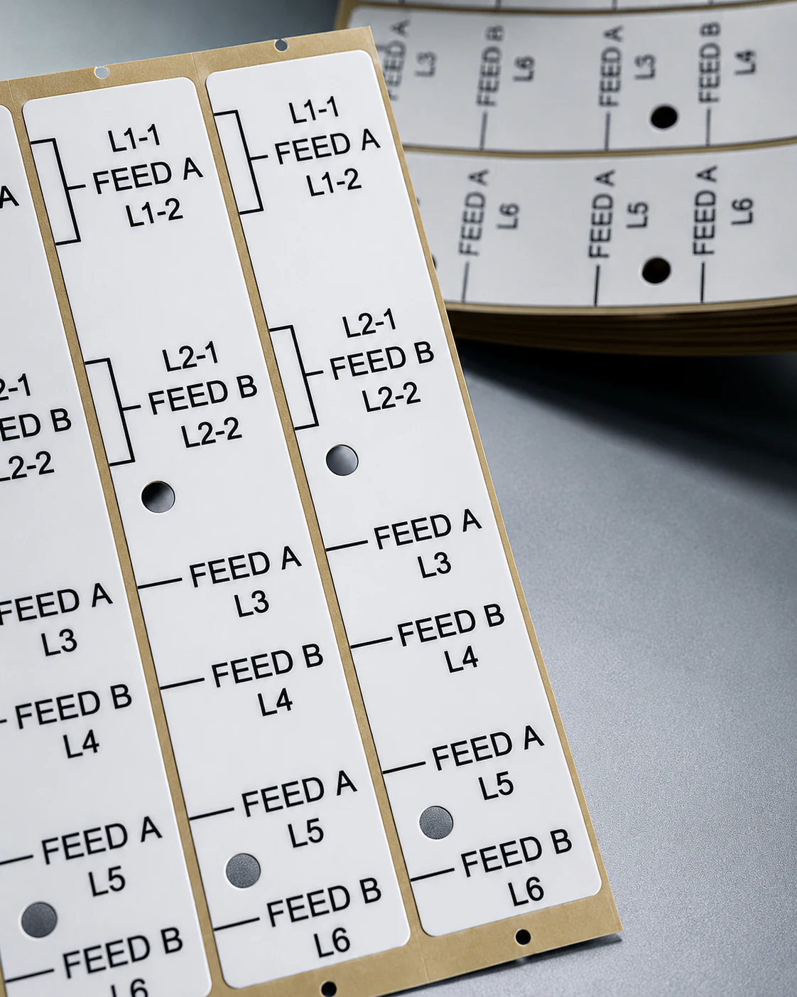
Liner split, tab, and presentation layout reviewed to support removal behavior and manual or semi-automated application.
Materials & Formats
Materials We Convert
Precision converting routes are selected according to film thickness, foam compression, adhesive flow, liner release, and stack-up requirements.
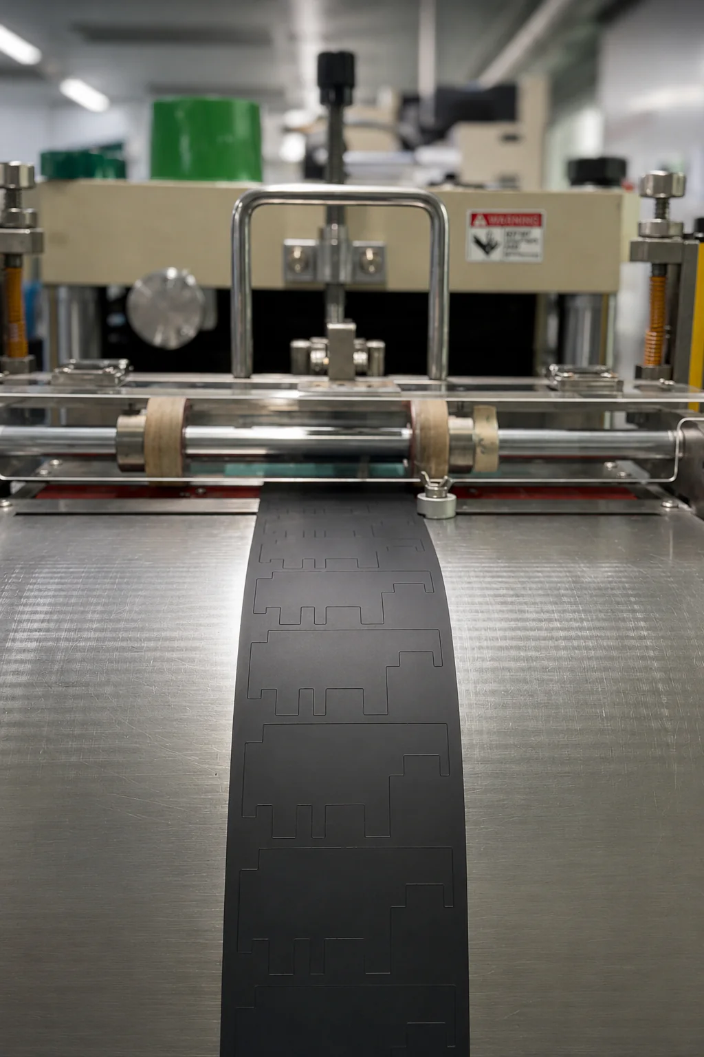
FUNCTIONAL MATERIAL CONVERTING
Functional Material Converting
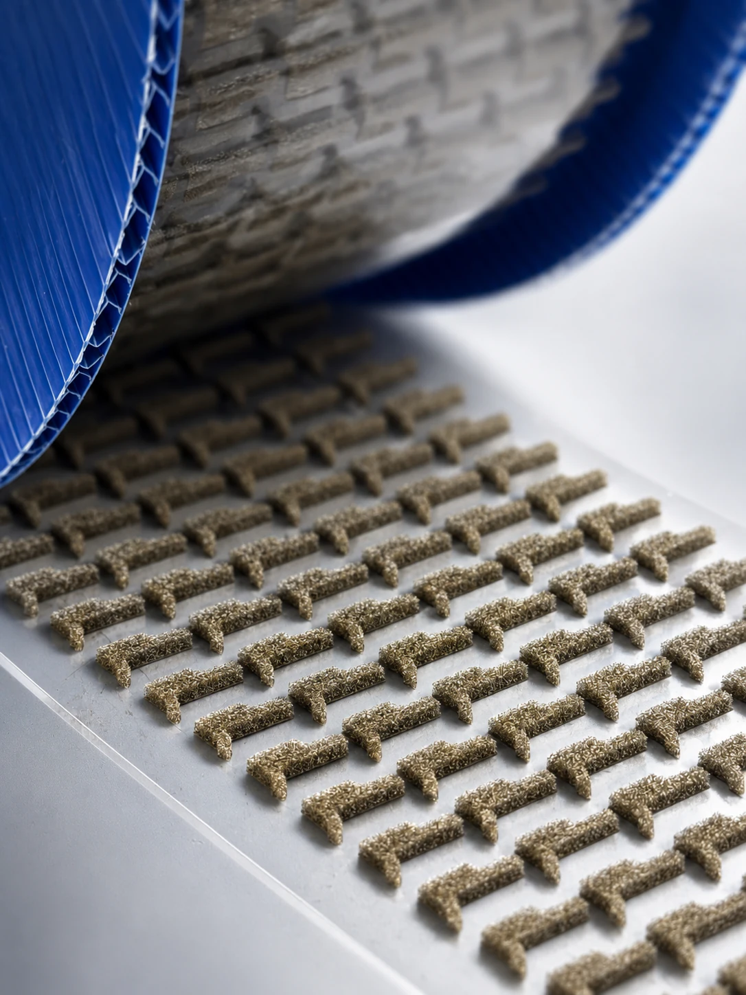
Graphite sheets, insulation films, and adhesive-backed layers are reviewed for thickness, release behavior, cutting stability, and component geometry before production release.
Typical Applications
Typical Applications
APP 01
Adhesive gaskets
APP 02
Foam spacers
APP 03
Insulation films
APP 04
Protective films
APP 05
Graphite thermal components
APP 06
EMI shielding pads
APP 07
Multi-layer laminated parts
APP 08
Custom converted components
Process & Quality Control
Process & Quality Control
STEP 01
Drawing Review
Geometry, tolerance, and cut path are reviewed against material behavior and application requirements before tooling.
STEP 02
Material & Stack-Up Review
Films, adhesives, liners, and laminated constructions are checked for thickness, compression, release, and assembly fit.
STEP 03
Tooling / Cutting Setup
Flatbed or rotary route is selected according to part geometry, volume target, and converting stability.
STEP 04
First Article Check
Initial parts are reviewed for cut quality, dimensional alignment, liner release behavior, and process readiness.
STEP 05
Batch Production & Release
Production runs proceed with dimensional inspection, visual checks, process verification, and controlled release records.
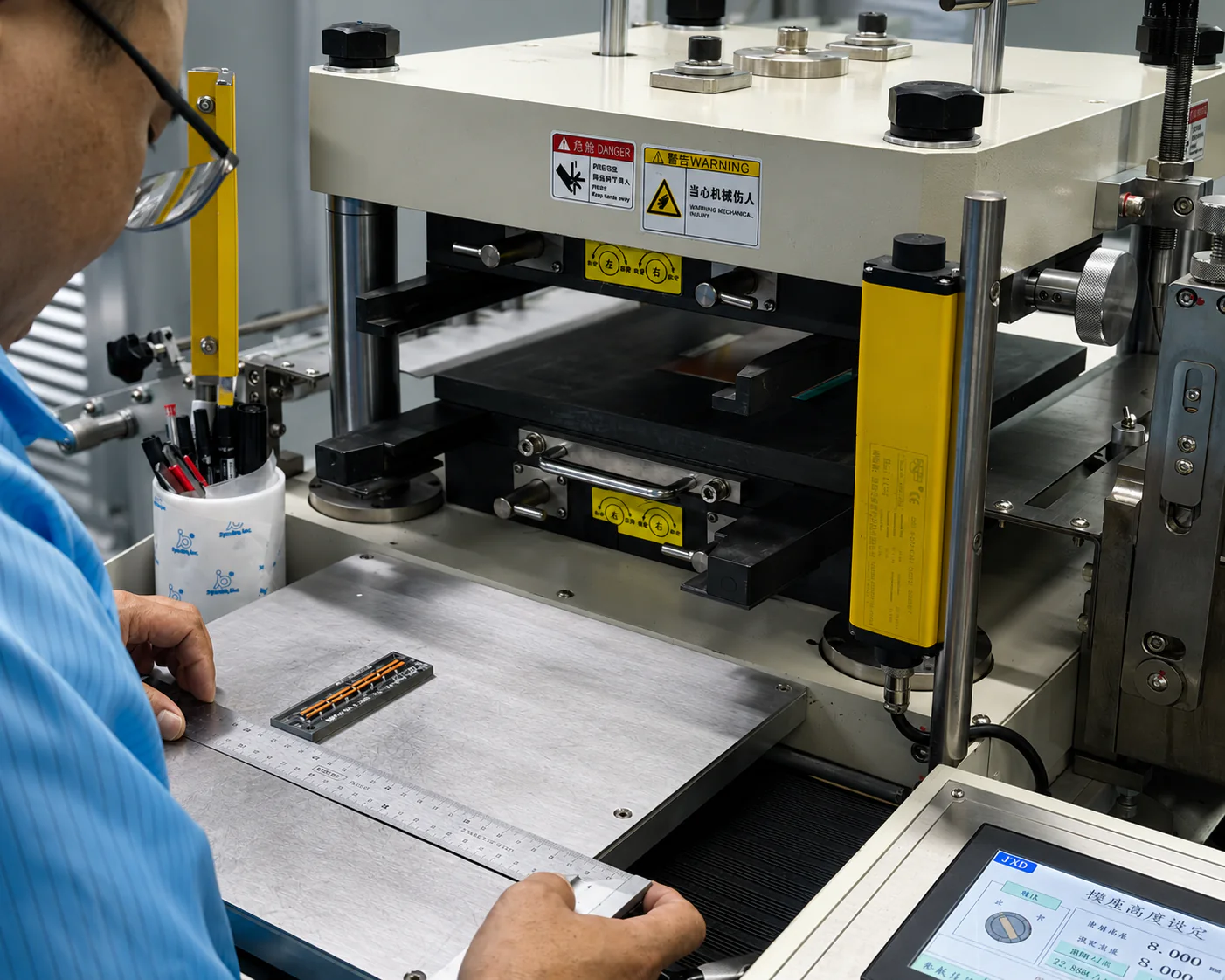
OPERATOR PROCESS CHECK
Inspection points are established according to part geometry, material construction, liner behavior, and OEM release requirements.
Need Support for a Precision Die-Cutting Program?
Share drawings, materials, tolerances, or sample requirements. Our team can review manufacturability, material fit, and production route for your converted components.