
Industrial Operator Panel / Industrial Controls

Industrial Control Panel Overlay with Backlit Indicator Windows

A printed control panel overlay construction combining backlit indicator windows, protective surface layers, adhesive support, and precision-converted geometry.

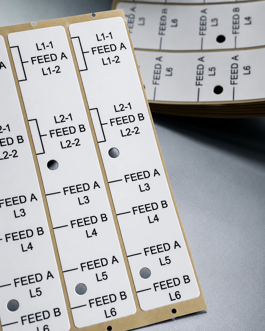
Printed graphic overlay with backlit indicator windows for an industrial control panel
Representative converted component formats for this application type.

PROJECT SNAPSHOT

Application

Industrial operator panel with printed legends and backlit indicator windows

Materials

Printed overlay film, transparent or diffused window layers, adhesive constructions, and protective surface films

Converting Processes

Artwork review, print registration, window preparation, lamination, and precision conversion

Verification Focus

Printed legend alignment, window position, backlit indicator visibility, converted geometry, and assembly fit

ENGINEERING RESPONSE

Project Approach

APPROACH_01

Challenge

Industrial operator panels combine printed legends, closely spaced indicator windows, adhesive layers, and converted outer geometry. The printed and transparent areas must remain aligned so illuminated indicators are visible in the intended locations without distracting overlap between neighboring graphics or interference during assembly.

APPROACH_02

Engineering Response

Labelsun reviews artwork, indicator locations, window and diffusion layer options, light-blocking zones, adhesive coverage, print registration, and die-cut geometry before prototype preparation. The printing and conversion route is planned around the panel layout, backlighting arrangement, and assembly conditions.

APPROACH_03

Converted Output

Application-specific printed control panel overlays with prepared indicator windows, adhesive support, protective surface layers, and converted apertures are prepared for prototype review and controlled production preparation.

DEVELOPMENT ROUTE

Development & Verification Route

STEP 01

Artwork & Backlight Review

Review printed legends, indicator locations, window zones, control features, adhesive coverage, and panel assembly requirements.

STEP 02

Layer & Window Planning

Evaluate overlay film, transparent or diffused layers, light-blocking areas, protective surface films, and adhesive construction.

STEP 03

Prototype & Indicator Review

Prepare samples and review legend registration, window position, indicator visibility, converted geometry, and assembly fit.

STEP 04

Process Preparation & Release

Confirm the approved artwork, layer construction, printing and converting route, inspection focus, and production-release requirements.

VERIFICATION & RELEASE

Verification & Production Release

Verification focuses on printed legend registration, indicator window position, visible backlight behavior under the agreed review conditions, converted dimensions, surface condition, and assembly fit. Production release records reflect the approved artwork and layer construction.

Printed legend alignment
Indicator window position
Backlit visibility review
Surface visual inspection
Converted geometry verification
Assembly-fit and release record review

RELATED CAPABILITIES

Related Manufacturing Capabilities

START A SIMILAR PROGRAM

Discuss a Similar Manufacturing Program

Share drawings, material stack-up requirements, assembly conditions, or sample needs for engineering review.